High-speed spinning equipment depends on stable spindle rotation, accurate alignment, and controlled bearing conditions. When vibration appears, the machine often gives small warnings first: a sharper sound, uneven yarn tension, rising bearing temperature, or repeated end breakage. The keyword “how to troubleshoot spindle vibration in high speed spinning equipment” describes a practical investigation, not a single repair step. Each symptom requires measurement and context.
Dr. S. M. Ishtiaque, a textile engineering researcher, has emphasized, “Small changes in spindle vibration can reveal large changes in machine condition.” That principle guides this troubleshooting process. Technicians should compare vibration readings across adjacent spindles, inspect the spindle tape, check bearing clearance, and confirm rotor balance. An accelerometer can expose frequency peaks that human hearing misses. Useful data includes speed, load, temperature, vibration amplitude, and maintenance history.
Do not guess too quickly.
A loose component may imitate bearing damage. A worn tape may resemble misalignment. Dust around the spindle can also distort observations. These details are easy to overlook during production pressure. The most reliable approach combines operator experience, calibrated instruments, manufacturer limits, and documented trend data. Still, no checklist is perfect. Sensor placement may vary, and a brief measurement can hide an intermittent fault. This guide therefore focuses on disciplined inspection, repeatable testing, and careful judgment. It also recognizes an uncomfortable reality: some vibration problems remain unclear until the machine is stopped and examined directly.
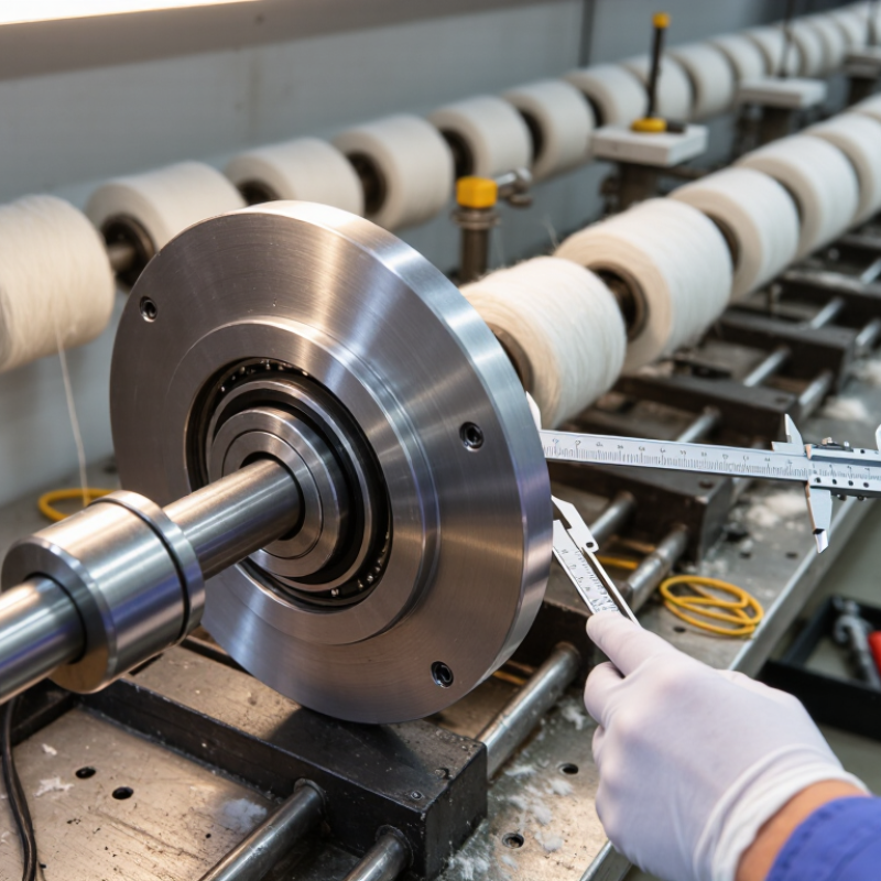
Spindle vibration is the repeated movement of a spinning spindle away from its intended centerline. In high-speed spinning equipment, slight movement can become serious within seconds. It may come from imbalance, worn bearings, poor alignment, loose mounting, or an uneven load. The vibration often changes with speed.
Common symptoms are easy to notice when operators know what to watch. You may hear a rising hum, clicking, or a rough metallic sound. The spindle housing may feel warmer than usual. Yarn tension can become unstable, causing irregular winding, broken fibers, or visible surface defects. You might also see fine movement around the spindle tip. It looks minor. It may not.
From practical inspections, vibration usually leaves several clues at once. A vibration meter can confirm frequency and amplitude, while a visual check can reveal loose fasteners or contamination. Do not rely on touch alone at high speed. It is useful, but not precise enough.
Tips: Stop the machine if vibration increases suddenly. Check the spindle load, mounting bolts, bearing condition, and alignment after isolation. Compare readings with the equipment’s normal baseline. Record speed, temperature, noise, and vibration together. A neglected baseline is a common mistake. Also, inspect nearby spindles, because shared mounting or drive conditions may affect more than one unit.
Spindle vibration often starts with a small setup error. Check spindle runout with a certified test bar before changing cutting parameters. ISO 230-1 allows geometric accuracy checks under defined measurement conditions. Use the same conditions every time. A dirty taper, damaged pull stud, or uneven toolholder contact can create visible marks within minutes. Clean both mating surfaces carefully. Then verify tool balance at the intended operating speed. A 2022 CIRP review reported that chatter can reduce effective material removal rates by roughly 20–40%. That loss is expensive, but the vibration pattern usually gives clues.
Inspect tooling next. Shorten tool overhang whenever possible. A long carbide tool can behave like a flexible spring. The common overhang-to-diameter ratio should stay near four-to-one, though the workpiece may force compromises. Check insert seating, edge damage, and uneven wear under magnification. Workholding deserves equal attention. Measure jaw contact, fixture rigidity, and clamping pressure. Thin walls can deform before cutting begins. According to a 2023 machining-monitoring study in the Journal of Manufacturing Processes, force and vibration signals can identify unstable cutting before visible surface damage appears. Use accelerometer trends, not only sound. I once blamed the spindle bearings too early. The actual problem was a slightly lifted fixture jaw. Recheck the basics, even when the machine sounds sophisticated.
| Inspection Dimension | Typical Symptom or Measurement | Recommended Check | Practical Acceptance Guideline | Corrective Action | Priority |
|---|---|---|---|---|---|
| Spindle warm-up and operating state | Vibration increases immediately after startup or changes as the spindle reaches speed. | Record vibration at low, medium, and maximum operating speed after the machine reaches its normal warm-up condition. | Use the machine builder's warm-up procedure and compare readings with the machine's established baseline. | Run the prescribed warm-up cycle, verify lubrication, and avoid precision cutting before thermal stabilization. | Medium |
| Spindle speed and resonance | A sharp vibration peak appears only within a narrow speed range. | Perform a controlled speed sweep and identify whether the vibration follows spindle speed or remains at a fixed frequency. | Do not operate continuously at a speed where vibration rises sharply; use a nearby stable speed during diagnosis. | Adjust cutting speed, tool length, or holder configuration to move the operating point away from the resonance zone. | High |
| Spindle taper cleanliness | Runout or vibration appears after tool changes, often with inconsistent results. | Inspect and clean the spindle taper, toolholder taper, and retention knob contact surfaces. | Surfaces should be free of chips, coolant residue, raised dents, and visible damage. | Clean with lint-free materials and approved procedures; replace damaged tooling or repair damaged taper surfaces. | High |
| Toolholder seating and retention | Vibration changes when the same tool is reinstalled or when clamping force varies. | Check full taper contact, retention mechanism condition, pull-stud security, and holder seating. | The holder must seat firmly without rocking, visible gaps, or abnormal marks at the flange or taper. | Correct the seating problem, replace worn retention components, and verify the clamping system before cutting. | High |
| Tool and holder runout | Cutting edges show uneven wear, chatter marks, or a repeating pattern on the workpiece. | Measure radial runout near the holder and near the cutting zone using a calibrated indicator. | For high-speed precision work, a common target is approximately 0.01 mm or less at the cutting location, subject to the tooling specification. | Clean and reseat the tool, inspect collets, and replace bent, worn, or incompatible holders and collets. | High |
| Tool length and overhang | Vibration becomes worse as the tool extends farther from the spindle. | Compare the actual tool overhang with the minimum length required for the operation. | Reduce overhang whenever possible; bending stiffness decreases rapidly as unsupported length increases. | Shorten the tool assembly, use a more rigid holder, reduce radial engagement, or select a suitable tool diameter. | High |
| Tool balance at operating speed | Vibration increases with rotational speed and produces a strong once-per-revolution component. | Check whether the complete rotating assembly is balanced as a unit, including holder, collet, nut, and tool. | Use the balance quality and maximum speed rating specified for the complete tool assembly; do not rely on the tool alone. | Balance or replace the assembly, remove asymmetric contamination, and never exceed the lowest rated component speed. | High |
| Collet and clamping condition | The tool slips, produces variable runout, or vibrates despite a clean spindle taper. | Inspect collet slots, nut threads, contact surfaces, and tightening method. | Collets should be undamaged, correctly matched to the tool diameter, and tightened using the specified procedure. | Replace damaged or fatigued collets, clean the nut, and apply the correct tightening force with suitable equipment. | High |
| Workholding rigidity | Vibration is low without a workpiece but increases substantially during cutting. | Check fixture stiffness, jaw or clamp contact, support points, and the relationship between the cutting force and the workholding layout. | The workpiece should be supported close to the cutting zone with no rocking, gaps, or flexible unsupported sections. | Add support, reduce unsupported length, improve contact, or use a more rigid fixture and clamping arrangement. | High |
| Workpiece projection and wall thickness | Chatter is concentrated on thin walls, long projections, or low-mass workpieces. | Evaluate workpiece stiffness and measure deflection during clamping and cutting. | Minimize projection and avoid clamping forces that distort the part or leave insufficient structural support. | Change the support strategy, use softer or shaped jaws, reduce radial engagement, and use lighter cutting passes. | Medium |
| Cutting parameters | Vibration begins when radial engagement, axial depth, feed, or cutting force increases. | Change one parameter at a time while monitoring vibration and surface finish. | Use a stable speed range and keep cutting forces within the tool, holder, spindle, and workholding capability. | Reduce radial engagement or depth of cut, adjust feed per tooth appropriately, and avoid unnecessarily aggressive full-slot cutting. | Medium |
| Tool condition and geometry | Vibration is accompanied by edge chipping, flank wear, built-up material, or irregular cutting noise. | Inspect all cutting edges under adequate lighting and compare wear between edges. | Edges should be consistent and free from chipping, excessive wear, and built-up material. | Replace or recondition the tool, correct coolant delivery, and select geometry suited to the material and operation. | Medium |
| Coolant and chip evacuation | Vibration varies with chip packing, intermittent cutting, or unstable coolant flow. | Check nozzle position, flow consistency, chip evacuation, and recutting of chips. | The cutting zone should remain clear enough to prevent chip recutting and sudden load changes. | Improve coolant direction and flow, clear chip accumulation, and modify the toolpath or cutting parameters if necessary. | Medium |
| Spindle bearings and mechanical condition | Vibration remains high without cutting, increases with speed, or is accompanied by abnormal noise or heat. | Measure vibration with the spindle unloaded and compare axial, radial, and housing temperature trends with the baseline. | A sudden increase from the established baseline, abnormal bearing noise, or excessive temperature requires immediate investigation. | Stop high-speed operation if conditions worsen and have the spindle, lubrication system, and bearings inspected by qualified service personnel. | High |
| Measurement method and baseline | Different operators obtain conflicting vibration readings or conclusions. | Use the same sensor location, measurement direction, spindle speed, warm-up state, and data-collection method. | Compare like-for-like readings and document speed, tool assembly, workholding, material, and cutting conditions. | Create a machine-specific baseline and trend vibration over time instead of relying on a single reading. | Low |
At high speed, spindle vibration should be measured before any adjustment is made. The visible symptom is often not the real source. A loose foundation, worn bearing, imbalance, or coupling misalignment may create similar movement.
Use a calibrated vibration sensor and measure radial and axial directions. Take readings at the spindle housing, bearing seats, motor mount, and machine frame. Record speed, temperature, load, and operating time. Frequency analysis can separate running-speed vibration from bearing or belt-related frequencies. A strong peak at running speed may indicate imbalance. Axial movement often suggests misalignment or excessive preload. Keep the machine condition consistent.
Compare readings between nearby points. The highest amplitude usually provides a useful clue, but not absolute proof. A damaged cover or loose guard can amplify vibration and confuse the diagnosis. One practical mistake is trusting a single measurement. Sensor placement, cable movement, and surface condition can distort the result. Repeat the test after repositioning the sensor.
After locating the likely source, inspect physical conditions carefully. Check fasteners, shaft runout, bearing clearance, lubrication condition, and tool holding surfaces. Correct one factor at a time, then measure again at the same speed and load. If vibration falls only briefly, the repair may have treated the symptom. Thermal growth can also change alignment during operation, so cold measurements may be incomplete. A reliable record should include waveform, spectrum, machine state, and the technician’s observations.
Measure vibration sources and compare frequency components to locate the most likely root cause. The chart shows representative RMS vibration velocity measured at the spindle housing during a 12,000 rpm test.
Unbalance commonly appears at 1× rotational frequency, while misalignment often increases 2× vibration. Bearing-related vibration is typically stronger in higher-frequency bands, and tool or collet resonance can produce a broad response near the system's natural frequency.
How to Troubleshoot Spindle Vibration in High Speed Spinning?
Start with speed. I usually reduce spindle speed in 5% steps and record vibration at each setting. A sharp increase near one speed often indicates resonance, not simple imbalance. The vibration spectrum should be checked for a dominant 1× rotational-frequency peak. This pattern commonly points to imbalance. ISO 20816-1:2016 recommends evaluating machine vibration through measured RMS velocity, but acceptance limits depend on machine type and installation. Do not rely on one universal number. That shortcut can mislead.
Balance the rotating assembly according to ISO 21940-11:2016. Clean the taper, inspect the tool holder, and measure runout with a dial indicator. A small chip under the mounting face can create visible movement at high speed. Check alignment, soft foot, coupling condition, and foundation stiffness. Then inspect bearings for abnormal temperature, noise, preload changes, and lubrication problems. The U.S. Department of Energy’s Operations & Maintenance Best Practices report identifies potential maintenance-cost savings of 8–12% through predictive maintenance. Vibration trending supports that approach. Still, a single reading is weak evidence. Record speed, load, temperature, axial vibration, and radial vibration together. My earlier habit was checking only radial vibration. It was incomplete.
How to Troubleshoot Spindle Vibration in High Speed Spinning?
Verify the Repair Through Testing and Preventive Maintenance
After repairing a vibrating spindle, do not trust a quiet first run. A stable test is essential. Record vibration at the drive end and non-drive end. Measure radial and axial values separately. Capture readings during acceleration, operating speed, and shutdown. Watch the temperature near the bearing housing. A small rise may reveal preload, lubrication, or alignment problems.
Compare every result with the machine’s historical baseline and ISO 20816 guidance. ISO limits depend on machine class, support structure, and measurement position. One number cannot prove a repair. The U.S. Department of Energy’s Operations & Maintenance Best Practices Guide reports that predictive maintenance can reduce downtime by 35–45% compared with reactive maintenance. It also estimates maintenance cost savings of 8–12% against routine preventive work. These figures guide decisions, not guarantees.
Use a calibrated analyzer and document sensor placement. Check coupling alignment, balance quality, bearing condition, and fastener torque. Repeat the test after several production cycles. A spindle may pass at 12,000 rpm, then vibrate after thermal expansion. That detail is easy to miss. One practical mistake is testing only without a load. Real material tension can change the vibration pattern. Set alarm levels from verified baseline trends, not guesswork. Review readings weekly, inspect lubrication intervals, and schedule a deeper inspection when amplitude rises consistently. The repair may be correct. The test may still be incomplete.
Spindle vibration is repeated movement away from the intended centerline. It often changes as operating speed changes. Small movement can become serious quickly.
Listen for a rising hum, clicking, or rough metallic noise. The housing may feel unusually warm. Fine movement near the spindle tip is another warning.
Unstable vibration may disturb yarn tension, break fibers, or create uneven winding. In machining, it can leave visible surface marks. Cutting efficiency may also decrease.
Stop the machine and isolate it safely. Check the load, mounting bolts, bearings, and alignment. Do not rely on touch alone.
Use a vibration meter to record frequency and amplitude. Compare readings with the normal equipment baseline. Record speed, temperature, noise, and vibration together.
Dirty mating surfaces, damaged retaining parts, poor alignment, and loose mounting can cause vibration. Check spindle runout with a certified test bar. Use consistent measurement conditions.
Long tool overhang can make a tool act like a flexible spring. Keep the overhang-to-diameter ratio near four-to-one when practical. Also check insert seating, jaw contact, fixture rigidity, and clamping pressure.
Yes, shared mounting or drive conditions may affect nearby spindles. Inspect adjacent units instead of checking only one spindle. Check basics.
Do not change cutting parameters before checking runout and setup. A lifted fixture jaw may imitate a bearing problem. I once blamed the bearings too early. Recheck the simple causes.
How to troubleshoot spindle vibration in high speed spinning equipment begins with recognizing symptoms such as unusual noise, visible shaking, poor surface finish, dimensional errors, or accelerated tool and bearing wear. Start by checking the spindle setup, tooling, collet or chuck condition, workholding stability, and material clamping. Loose components, uneven loading, damaged tools, or improper overhang can quickly create or amplify vibration.
Next, measure vibration at different speeds and locations to identify whether the source is imbalance, misalignment, resonance, bearing deterioration, or an unstable connection. Corrective actions may include adjusting the operating speed, balancing the rotating assembly, improving alignment, reducing tool overhang, tightening workholding components, or inspecting and replacing worn bearings when necessary. After repairs, verify performance through controlled test runs, gradually increasing speed while monitoring noise, vibration, temperature, and machining quality. Preventive maintenance should include regular cleaning, inspection, balancing checks, lubrication control, and vibration trend recording to detect problems before they become serious.

ZRF Spinning