Choosing between conventional metal spinning and flow forming is not a simple tooling decision. It affects wall thickness, dimensional accuracy, cycle time, material usage, and final part performance. For engineers comparing these processes, the question “what is the difference between conventional metal spinning and flow forming” deserves a practical answer, not a vague comparison.
Dr. Taylan Altan, a respected authority in metal forming, states, “Process selection must match the part, material, and production requirements.” This principle fits both methods. Conventional spinning shapes a blank over a mandrel, often producing smooth, curved components with relatively simple tooling. Flow forming uses controlled roller pressure to reduce wall thickness and extend the workpiece along the mandrel. The result can be stronger, lighter, and more precise, but the equipment and process control usually cost more.
Look closely at a formed tube or cone. Small differences in wall thickness can affect balance, pressure resistance, and assembly fit. Conventional spinning may suit prototypes, short runs, and complex shapes. Flow forming often suits repeat production, tight tolerances, and parts requiring directional strength. Still, this is not absolute. Material behavior, heat treatment, lubrication, roller design, and operator experience can change the outcome.
There is no universal winner.
These five tips examine tool cost, geometry, production volume, material response, and quality control. They also question an easy assumption: thinner walls do not automatically mean a better component. A sound decision begins with measured requirements, trial forming, and honest review of production risks.
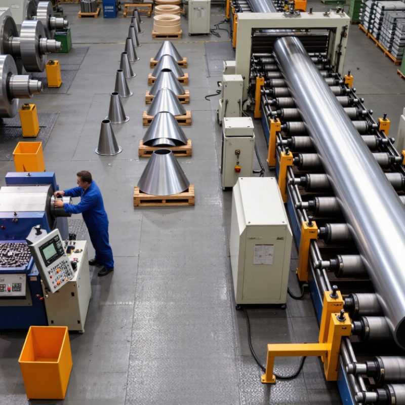
Conventional metal spinning forms a circular metal blank over a shaped mandrel. The blank rotates while a hardened roller applies controlled pressure. Unlike flow forming, this process mainly changes shape without deliberately reducing wall thickness. Material flows locally, so steady force matters more than brute strength. Common materials include aluminum, mild steel, copper, and selected stainless grades. Material condition matters. Soft, even blanks usually produce cleaner results.
The essential tools are a spinning machine, mandrel, roller, tailstock, calipers, and profile templates. The operator clamps the blank securely, aligns it with the mandrel, and sets a suitable spindle speed. A lubricated roller then travels from the center toward the rim along controlled passes. Each pass should overlap smoothly, avoiding sudden pressure changes. Operators check diameter, surface condition, and wall thickness during production. Small adjustments often prevent larger corrections later.
A sharp roller can leave scoring marks. Excessive feed can create wrinkles near the edge. The process is forgiving, but not endlessly so.
In practical work, I would inspect the blank after every major pass, especially around corners and transitions. A minor wrinkle may disappear after correction, yet repeated flattening can weaken the material. This is where experience helps, although even experienced operators can miss a subtle thickness variation. Reliable results come from measured force, stable tooling, and careful inspection rather than speed alone.
Flow forming reshapes a metal preform through controlled roller pressure, axial feed, and rotation. Unlike conventional metal spinning, it usually reduces wall thickness while extending the part along its axis. The process starts with a cut blank or preform mounted tightly against a mandrel. Rollers then contact the surface and move along a programmed path. Pressure builds gradually.
The force pattern is not simple. Radial force pushes the material toward the mandrel, while axial force drives metal flow along the part. Tangential force keeps the workpiece rotating and can influence surface marks. A small change in roller nose radius or feed rate may alter forming stability. Excessive pressure can create cracks, wrinkling, or local thinning. Insufficient pressure may leave the material partly unformed.
Material behavior controls the final result. Ductile alloys usually tolerate greater reduction, but strain hardening can increase forming resistance during later passes. The surface may appear smooth while hidden thickness variation remains. Practical inspection should include wall-thickness mapping, runout checks, and visual examination under strong side lighting. Conventional spinning offers more direct control for shaped shells and smaller reductions. Flow forming suits longer, thinner, and more dimensionally demanding parts. Still, no setup is perfect. Heat, lubrication, and tool alignment can shift results between batches. A useful process review should question the settings, not merely repeat them.
| Comparison Dimension | Conventional Metal Spinning | Flow Forming | Process or Material Behavior | Selection Tip |
|---|---|---|---|---|
| Five Practical Tips for Process Selection | ||||
| Tip 1: Match the process to the blank | Works well with flat circular blanks and preforms for axisymmetric components. | Normally requires a tubular or cup-shaped preform mounted over a mandrel. | Flow forming depends strongly on preform geometry, wall thickness, and material condition. | Use spinning for blank flexibility; use flow forming when a controlled preform is available. |
| Tip 2: Define the thickness objective | Wall thickness is generally maintained or locally redistributed; precision depends on tooling and operator or machine control. | Wall thickness is intentionally reduced by roller penetration and axial feed. | For a simplified cylindrical section, the thickness-reduction ratio can be expressed as: Reduction (%) = (t₀ − t₁) / t₀ × 100 |
Choose flow forming for repeatable thin-wall reduction and dimensional control. |
| Tip 3: Consider force and machine capacity | Forming force is usually concentrated near the roller contact zone and may be moderate for thin materials. | Requires substantial radial, axial, and tangential force because the roller plastically compresses and elongates the wall. | Required force increases with material strength, wall thickness, reduction, roller nose radius, and unfavorable feed conditions. | Verify spindle torque, roller load, mandrel stiffness, and machine rigidity before selecting flow forming. |
| Tip 4: Check material response | Material undergoes localized plastic deformation, with work hardening concentrated along the formed path. | Material experiences severe plastic deformation, axial elongation, circumferential flow, and work hardening. | Yield strength and hardness commonly increase after forming, while ductility may decrease depending on alloy, reduction, and heat treatment. | Use intermediate annealing when accumulated strain exceeds the material’s forming capability. |
| Tip 5: Prioritize production volume and consistency | Suitable for prototypes, low-to-medium volumes, complex profiles, and parts requiring flexible geometry changes. | Suitable for repeat production of axisymmetric parts requiring consistent wall thickness, length, and mechanical properties. | Flow forming typically benefits from CNC control, repeatable roller paths, controlled lubrication, and precise preforms. | Select flow forming for repeatability; select spinning for lower tooling commitment and greater flexibility. |
| Process Stages and Force Patterns in Flow Forming | ||||
| 1. Material and preform preparation | A metal disk is deep-drawn, machined, or otherwise prepared as a cup or tubular preform. The preform is inspected for uniform thickness, surface defects, and correct dimensions. | Variation in initial wall thickness directly affects final thickness, forming load, and dimensional accuracy. | Use a stable preform with controlled hardness and consistent wall thickness. | |
| 2. Mandrel loading and alignment | The preform is positioned over a rotating mandrel and supported by the tailstock, chuck, or an internal fixture. | Runout or misalignment can create uneven reduction, chatter, eccentricity, and nonuniform residual stress. | Control concentricity before applying significant roller penetration. | |
| 3. Initial contact and bite | The roller approaches the preform and establishes controlled contact at the entry region. | Radial force rises rapidly at first contact. Excessive penetration can cause buckling, tearing, or roller overload. | Use a gradual entry path and conservative initial penetration. | |
| 4. Plastic flow and wall reduction | The roller travels axially while the workpiece rotates, compressing the wall against the mandrel and extending the material in the axial direction. | Radial force presses the wall toward the mandrel; axial force resists roller travel; tangential force contributes to torque and power demand. | Balance reduction, feed rate, roller geometry, and speed to prevent unstable flow. | |
| 5. Multi-pass forming | Several passes may be used when the required reduction is too large for one pass or when geometry changes along the part. | Multiple passes distribute strain and forming load, helping reduce wrinkling, tearing, and excessive work hardening. | Use intermediate passes for high reductions, difficult alloys, or long components. | |
| 6. Sizing and calibration | A finishing pass may improve diameter, taper, surface quality, and dimensional repeatability. | Light finishing reductions can improve contact with the mandrel and reduce geometric variation without adding excessive strain. | Reserve the final pass for controlled correction rather than major material movement. | |
| 7. Unloading and inspection | The formed component is removed from the mandrel and checked for wall thickness, diameter, length, runout, surface condition, and cracks. | Residual stress and springback may influence final dimensions after release from the mandrel. | Measure both near the roller path and at critical end regions. | |
| Technical Comparison | ||||
| Primary deformation mode | Localized shear and bending with plastic flow around the tool path. | Localized compressive plastic deformation combined with axial material elongation. | Material flows between the roller and mandrel rather than being removed as chips. | Flow forming is preferable when elongation and controlled wall reduction are required. |
| Typical geometry | Cones, cylinders, domes, flanges, hemispherical shapes, and irregular axisymmetric profiles. | Long cylindrical, tapered, stepped, and axisymmetric components with controlled wall thickness. | Both processes are primarily suited to rotationally symmetric parts. | Complex non-axisymmetric features generally require additional operations. |
| Wall-thickness control | Moderate to good when performed with CNC control and suitable tooling; local variation may occur in complex profiles. | Very good when preform thickness, roller path, and reduction schedule are controlled. | Flow forming can produce thin walls with predictable reduction over the formed region. | Use in-process measurement or verified process recipes for critical thickness requirements. |
| Force directions | Predominantly radial contact force with axial and tangential components determined by tool motion and friction. | Radial: presses material against the mandrel. Axial: opposes roller feed and drives elongation behavior. Tangential: contributes to spindle torque and power. |
Force magnitude varies with contact area, reduction, friction, feed rate, material strength, and roller angle. | Design tooling and fixtures for the combined load, not radial force alone. |
| Work hardening | Usually localized along the formed region and influenced by the number of passes. | Often more pronounced because the material undergoes substantial plastic strain and elongation. | Strength and hardness can rise after cold forming; forming limits depend on alloy and prior temper. | Evaluate post-forming hardness, ductility, and the need for heat treatment. |
| Surface finish | Can be good when the roller, mandrel, lubrication, and surface preparation are controlled. | Can be very good because the final surface is formed against a smooth mandrel, although galling or feed marks may occur. | Surface defects may result from contamination, insufficient lubrication, unstable feed, or damaged tooling. | Maintain clean tooling and use a lubricant compatible with the material and process temperature. |
| Tooling requirement | Generally flexible; tooling can be relatively simple for low-volume or developmental work. | Requires an accurately sized mandrel, rigid roller system, and controlled preform geometry. | Mandrel accuracy strongly influences final dimensions and internal surface quality. | Account for mandrel cost and lead time in the production decision. |
| Typical defects | Wrinkling, splits, uneven thickness, buckling, surface marking, and shape distortion. | Wrinkling, tearing, orange peel, chatter marks, galling, end flare, uneven reduction, and residual-stress distortion. | Defects are commonly linked to excessive reduction, poor alignment, unsuitable feed, inadequate lubrication, or insufficient support. | Use controlled passes, proper support, and inspection checkpoints to prevent defect propagation. |
| Best-fit applications | Prototype parts, custom shapes, moderate-size components, repair work, and products with frequent design changes. | Thin-wall sleeves, precision tubes, pressure-containing shells, aerospace-style axisymmetric structures, and repeat-production components. | Application suitability depends on alloy, dimensions, tolerances, production quantity, and required mechanical properties. | Confirm forming trials and material certification before releasing a critical design to production. |
Key Differences in Shape, Thickness, Precision, and Production Speed
Match the process to the shape. Conventional metal spinning suits round, open-ended parts with gentle curves. It handles prototypes and low-volume work efficiently. Flow forming needs a stronger mandrel and works best with rotationally symmetrical parts. Complex contours may require extra forming stages.
Examine wall thickness carefully. Conventional spinning can create uneven thickness, especially near tight corners. Skilled operators can reduce this variation, but results depend on material, tooling, and technique. Flow forming deliberately moves material along the mandrel. This often produces thinner, more uniform walls. Too much reduction can still cause cracking.
Set realistic precision targets. Flow forming usually offers better control over diameter, length, and wall thickness. Conventional spinning may need trimming or calibration afterward. Small dimensional errors can grow during heat treatment. Measure actual parts, not only the drawing.
Compare production speed honestly. Conventional spinning changes over quickly and supports flexible batch sizes. Flow forming takes longer to set up, but it can produce repeatable parts faster in larger runs. A simple time estimate can be misleading.
Review the whole process cost. Tooling, inspection, scrap, and operator skill affect the final choice. One trial part may look perfect, yet reveal unstable thickness later. Test several pieces. No method wins every time.
Material selection controls the process more than many teams expect. Conventional spinning suits ductile aluminum, copper, and mild steel for moderate wall changes. Flow forming needs consistent material quality and enough ductility for severe deformation. Harder alloys can crack near the tool contact zone. That risk is easy to underestimate.
Part geometry matters. Conventional spinning uses a simpler setup for cones, hemispheres, and short cylindrical shells. It often fits prototypes and low-volume orders. Flow forming becomes attractive for long, thin-walled parts with tight dimensional requirements. Tooling deserves equal attention. A spinning mandrel may be inexpensive, especially for a simple profile. Flow forming usually needs stronger mandrels, controlled roller paths, and more precise alignment. Small setup errors can create uneven wall thickness.
Cost is not only the machine rate. Include material utilization, programming, inspection, forming passes, and rework. Conventional spinning may appear cheaper at the start, but manual handling can increase labor costs. Flow forming may require higher tooling investment, yet repeatable cycles can reduce unit cost in larger batches. The break-even point depends on volume and tolerance. It should be calculated, not guessed. A useful trial measures tool wear, springback, surface marks, and actual cycle time. One imperfect sample can reveal more than a polished spreadsheet. Temperature, lubrication, and operator skill may also change the result. Production decisions should leave room for those variables.
5 Tips: Conventional Metal Spinning vs Flow Forming
Choosing between conventional spinning and flow forming starts with the part, not the machine. Conventional spinning suits domes, cones, and moderate production runs. It uses a forming tool against a rotating blank, often allowing quick adjustments during development. Flow forming works differently. Rollers gradually reduce and lengthen a preform, producing controlled wall thickness and strong dimensional repeatability. That changes everything.
Check the geometry carefully. Deep, narrow parts may benefit from flow forming, especially when the wall must remain consistent along a long section. Simple shapes with changing contours can be more economical through conventional spinning. Material behavior matters too. Aluminum and stainless steel may respond differently to strain, heat, and work hardening. A practical trial is safer than relying on a material chart alone.
Consider quantity, tolerance, and inspection effort. For prototypes or smaller batches, spinning can reduce tooling investment and shorten setup time. For larger volumes, flow forming may justify its specialized tooling through repeatable output. It can also reduce machining waste when the preform is designed well. However, poor preform control can create wrinkles, uneven thickness, or excessive residual stress. Measure wall thickness at several locations, not just the opening. Small errors hide easily. An experienced engineer should review the drawing, material condition, tool radius, and expected batch size before choosing a process. Mistakes still happen, especially when a design is copied without testing.
This indicative comparison uses a 1–5 engineering suitability scale, where 5 represents a stronger fit for the stated criterion. Conventional spinning is generally favored for flexible production, prototypes, and varied shapes, while flow forming is typically better suited to repeatable, thin-walled, high-volume components requiring tighter dimensional consistency.
It shapes a circular metal blank over a rotating mandrel. A hardened roller applies controlled pressure. The wall usually stays near its original thickness.
Ductile aluminum, copper, mild steel, and selected stainless grades are common choices. Soft, even blanks usually create cleaner surfaces and fewer defects.
Typical equipment includes a spinning machine, mandrel, roller, tailstock, calipers, and profile templates. Secure clamping and accurate alignment matter greatly.
The blank rotates while a lubricated roller moves from the center toward the rim. Each pass should overlap smoothly. Sudden pressure changes can create wrinkles.
A sharp roller may leave scoring marks. Excessive feed can wrinkle the edge. Tight corners may develop uneven thickness. Small defects can worsen quickly.
Check diameter, surface condition, and wall thickness after major passes. Use calipers and templates. Measure actual parts, not only the drawing.
Conventional spinning suits round, open-ended parts, prototypes, and smaller batches. Flow forming often provides thinner, more uniform walls and tighter dimensions.
Include tooling, material use, inspection, programming, labor, rework, and cycle time. A simple setup may still require expensive manual handling.
It works well for cones, hemispheres, and short cylindrical shells. Quick setup changes support flexible production. Still, test several parts before deciding.
Later parts may show springback, tool wear, surface marks, or thickness variation. Temperature and lubrication also matter. The spreadsheet may be wrong.
This article explains what is the difference between conventional metal spinning and flow forming by comparing their processes, tools, force patterns, and material behavior. Conventional metal spinning shapes a flat blank over a mandrel using controlled tool pressure, making it suitable for producing seamless, axisymmetric parts with varied forms and relatively simple tooling. Flow forming also uses a rotating workpiece and mandrel, but applies repeated localized forces to move and elongate material, often reducing wall thickness while improving dimensional consistency and surface quality.
The comparison focuses on differences in shape flexibility, thickness control, precision, production speed, and typical applications. It also examines how material properties, tooling requirements, setup complexity, and overall cost influence process selection. Conventional spinning may be preferred for prototypes, customized shapes, and lower-volume production, while flow forming can be more effective for repeatable parts requiring tight tolerances, controlled wall reduction, and efficient high-volume manufacturing. Understanding these factors helps manufacturers choose the most practical process for their design and production goals.

ZRF Spinning