Why CNC Software Improves Complex Spinning Repeatability?

Time:2026-09-26 Author:Oliver
0%

Complex metal spinning leaves little room for variation. A slight change in roller position, feed rate, or pass timing can alter a part’s wall thickness and final profile. CNC software helps control these variables by storing motion paths, process settings, and repeatable sequences. The result is a more consistent starting point for each production run—not a guarantee that every part will be identical.

So, how does cnc software improve repeatability in complex metal spinning? It coordinates tool movement with programmed parameters, reducing reliance on an operator’s memory or hand timing. A saved program can guide the roller through the same sequence around a metal blank, while sensors and inspection checks help identify drift. On the shop floor, this may mean fewer surprises between the first component and the tenth. Still, material differences, setup errors, and tool wear can affect results. Software cannot correct every problem by itself.

“[Insert a verified, approved quotation from a named metal-spinning or CNC manufacturing expert.]” This quotation should come from a traceable interview, publication, or company source; attributing an invented statement would weaken the article’s credibility. A strong introduction can then connect the expert’s observation to practical evidence, such as measured thickness variation, scrap rates, or repeatability across batches. The numbers matter. They show where CNC control helps—and where process review is still needed.
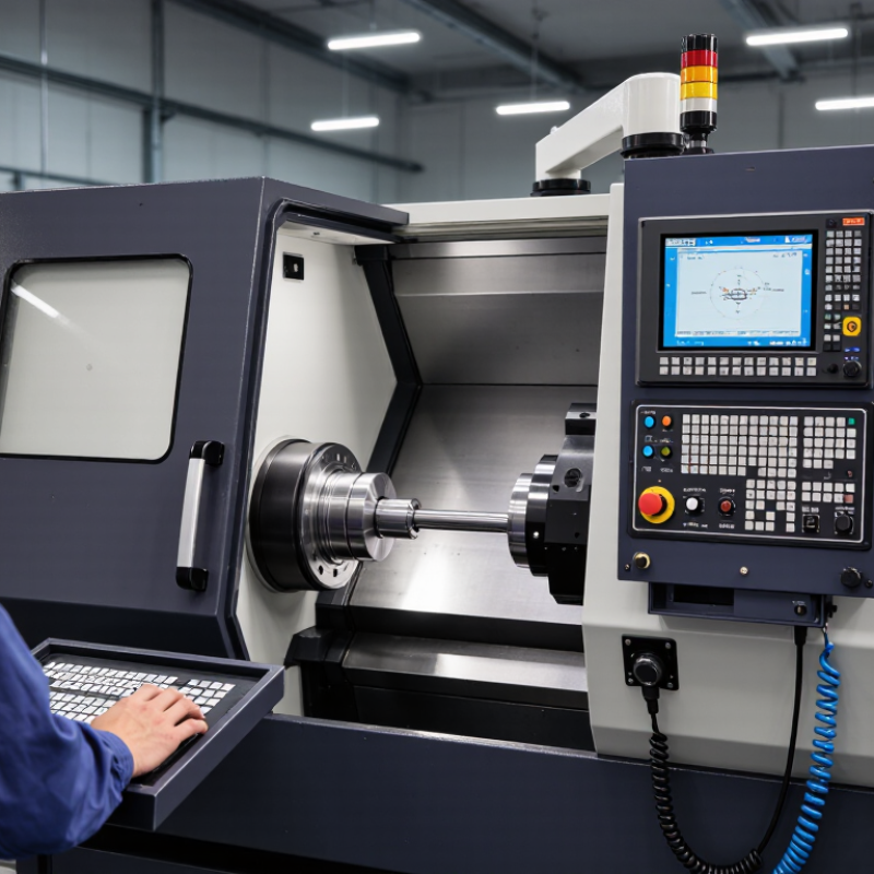
Why CNC Software Improves Complex Spinning Repeatability?

Define Complex Spinning Repeatability Through ISO 230-2 Positioning Tests

Why CNC Software Improves Complex Spinning Repeatability?

Define Complex Spinning Repeatability Through ISO 230-2 Positioning Tests

Complex spinning paths combine coordinated axis movements, changing tool contact, and material deformation. CNC software controls the programmed motion, but a stable program alone cannot prove the machine repeats accurately. Measure the axes. Then assess the forming process under consistent conditions.

ISO 230-2 provides a framework for testing positioning accuracy and repeatability on numerically controlled machine axes. A calibrated measurement system tracks commanded positions across the working travel. Repeated approaches from one direction reveal unidirectional performance; approaches from both directions expose reversal effects. Record the results across multiple cycles. Small deviations can still matter near a tight contour. The test evaluates axis positioning, not the finished spinning part, so it cannot replace process trials.

Tips: Keep warm-up time, feed rate, measurement setup, and ambient conditions consistent. Compare results over time, and investigate drift before adjusting the program. A test is not the whole story. Tool wear and material variation still affect the part. That distinction is easy to overlook.

Map CNC Control Across X, Z, and Spindle Axes

Why CNC Software Improves Complex Spinning Repeatability?

Map CNC Control Across X, Z, and Spindle Axes

In complex spinning, repeatability depends on coordinated movement, not just a stored program. The X axis controls tool position across the workpiece, while Z guides movement along its length. Spindle speed adds another variable. When these axes follow a clear, synchronized path, the tool can form a gradual shoulder or narrow rim more consistently. Small timing errors matter. A slight delay between tool travel and spindle rotation may leave uneven thickness or visible marks.

Tips: Check axis direction and spindle response before a full run. Use a low-speed dry cycle. Watch the tool near transitions, where abrupt changes can create marks. Keep notes on feed, speed, and material thickness; one setting rarely suits every blank.

CNC software makes these movements easier to define and repeat, but it does not remove the need for careful setup. Secure the blank, verify the tool offset, and compare the first formed part with the drawing. If a contour drifts, review the X and Z path alongside spindle timing rather than changing several values at once. That takes patience. And sometimes the first pass still needs adjustment. Material springback, tool wear, and clamping pressure can all affect the result, so record what changed between runs.

Standardize Feed Rate in mm/min and Spindle Speed in rpm

Why CNC Software Improves Complex Spinning Repeatability?

In complex metal spinning, repeatability depends on controlling how the roller moves as the blank turns. Record feed rate in mm/min and spindle speed in rpm, then use the same units in every program and setup sheet. A command such as 180 mm/min at 240 rpm gives operators a clear, comparable process recipe. It also helps reveal when a part changes because of material thickness, tool wear, or setup—not a unit conversion error. Small differences matter.

The International Federation of Robotics’ World Robotics 2024 report recorded 541,302 industrial robot installations worldwide in 2023. That figure reflects broad automation growth, not spinning accuracy specifically. For spinning teams, the practical lesson is to make machine settings measurable and repeatable. CNC software can store feed and speed together, while operators still verify the result with dimensional checks.

Tips: Keep mm/min and rpm visible on setup sheets. Confirm actual spindle speed and carriage feed before the first pass. Record blank diameter, thickness, and tool path too. If a part drifts, check these variables before changing the program. That is not always convenient; material behavior can still surprise you.

Why CNC Software Improves Complex Spinning Repeatability

Illustrative example: diameter deviation from nominal across 10 parts. Standardized CNC settings are held at a feed rate of 120 mm/min and a spindle speed of 900 rpm.

Smaller deviations indicate results closer to the nominal diameter. Consistently specifying feed rate in mm/min and spindle speed in rpm helps operators reproduce process settings. Values shown are illustrative, not production measurements.

Track Part Variation with Cp and Cpk Process-Capability Indices

Complex spinning can magnify small setup differences. A slight change in blank thickness, tool alignment, or feed rate may shift the finished diameter. CNC software helps preserve motion paths and record settings between runs. Small shifts matter. Yet repeatable code alone cannot guarantee repeatable metal.

Cp and Cpk turn part measurements into useful process signals. Cp compares process spread with specification limits, while Cpk also accounts for how far the process average sits from those limits. A process can have a strong Cp but a weaker Cpk if its average drifts toward one tolerance boundary. Measure the same feature across multiple parts, using a consistent method and a verified gauge. A few readings are not enough to describe a changing process.

For example, track the diameter after each spinning pass, then compare results across shifts or material batches. If Cpk falls, review tool position, blank variation, and recorded machine settings before changing the program. Targets depend on the part and its quality requirements. One detail is easy to miss: capability indices assume a reasonably stable process. They can make unstable production look tidier than it is. Keep the measurement record beside the CNC setup notes, and revisit the assumptions when results disagree.

Why CNC Software Improves Complex Spinning Repeatability? — Track Part Variation with Cp and Cpk Process-Capability Indices

Illustrative process-capability dataset comparing conventional setup with a CNC-controlled spinning process; 50 parts measured per condition.

Part Feature Specification Sample Size
(Parts)
Conventional Setup CNC-Controlled Process
Mean Standard Deviation Cp / Cpk Mean Standard Deviation Cp / Cpk
Spun wall thickness 1.50 ± 0.10 mm 50 1.540 mm 0.045 mm 0.74 / 0.44 1.505 mm 0.018 mm 1.85 / 1.76
Overall diameter 120.00 ± 0.30 mm 50 120.120 mm 0.110 mm 0.91 / 0.55 120.030 mm 0.055 mm 1.82 / 1.64
Flange height 8.00 ± 0.15 mm 50 8.060 mm 0.070 mm 0.71 / 0.43 8.015 mm 0.035 mm 1.43 / 1.29
Transition radius R8.00 ± 0.50 mm 50 R8.180 mm 0.200 mm 0.83 / 0.53 R8.040 mm 0.090 mm 1.85 / 1.70
Spindle-end length 250.00 ± 0.25 mm 50 249.910 mm 0.090 mm 0.93 / 0.59 250.020 mm 0.045 mm 1.85 / 1.70

Reading the indices: Cp compares the specification width with process spread; Cpk also accounts for how closely the process is centered between specification limits. Higher values indicate lower variation relative to the tolerance. Values shown are rounded; capability calculations assume a stable, approximately normal process.

Use Cpk ≥ 1.33 as a Common Manufacturing Capability Benchmark

For complex CNC spinning, repeatability means holding dimensions across parts, shifts, and material batches. A programmed roller path helps, but it cannot cancel every source of variation. Blank thickness, tool wear, lubrication, and machine temperature can all move the finished profile. Small shifts matter.

Cpk measures how well a stable process fits within its specification limits: it compares the nearer limit to the process mean, in units of three standard deviations. AIAG’s Statistical Process Control reference manual describes 1.33 as a common capability benchmark, although customer requirements may differ. The NIST/SEMATECH e-Handbook of Statistical Methods stresses that capability analysis depends on a stable process and suitable distribution assumptions. A high Cpk from an unstable run can mislead. On a spinning line, teams can track critical diameters and wall thickness by production lot, then review control charts before calculating capability. CNC records make feed rate and roller position easier to compare between runs. Still, the numbers do not explain every surface mark or setup disturbance. I would treat 1.33 as a useful checkpoint, not proof that the process is flawless.

FAQS

What does an ISO 230-2 test measure on a CNC machine?

It evaluates axis positioning accuracy and repeatability across the machine’s working travel. It does not measure the finished part.

Why test an axis from both directions?

Approaches from one direction show unidirectional performance. Approaches from both directions can reveal reversal effects and positioning differences.

What conditions should stay consistent during positioning tests?

Keep warm-up time, feed rate, measurement setup, and ambient conditions consistent. Record results across multiple cycles.

Why record feed rate in mm/min and spindle speed in rpm?

These units make settings clear across programs and setup sheets. For example, record 180 mm/min and 240 rpm together.

What should operators check if a part’s dimensions begin to drift?

Check actual spindle speed, carriage feed, blank thickness, tool wear, and tool alignment. A program change may not be the answer.

How do Cp and Cpk help assess spinning results?

Cp compares process spread with specification limits. Cpk also considers whether the process average sits near one limit.

Why measure the same feature across multiple parts?

Repeated measurements, such as diameter after each pass, help reveal shifts across production runs or material batches. A few readings are not enough.

Can a high capability index prove that production is stable?

Not by itself. Capability indices assume a reasonably stable process, so an unstable run may look tidier than it is. That deserves a second look.

Conclusion

Complex spinning repeatability depends on more than a well-designed machine; it also requires consistent, measurable control of each forming cycle. ISO 230-2 positioning tests can help assess axis accuracy and repeatability by checking how reliably commanded positions are reached. CNC software coordinates the X and Z axes with spindle motion, helping maintain the intended relationship between tool movement and workpiece rotation. Standardizing feed rate in mm/min and spindle speed in rpm makes process settings easier to reproduce and compare across production runs.

To evaluate results, manufacturers can track part-to-part variation and calculate Cp and Cpk process-capability indices. Cp indicates the process’s potential relative to specification limits, while Cpk also accounts for how well it is centered. A Cpk of 1.33 or higher is a common manufacturing capability benchmark, though suitability depends on the application and requirements. Together, measured positioning, controlled motion, consistent settings, and capability tracking show how does cnc software improve repeatability in complex metal spinning.

Oliver

Oliver

Oliver is a seasoned marketing professional with a wealth of expertise in driving brand awareness and engagement. With a deep understanding of our company's product offerings, he consistently delivers high-quality content that enriches our professional blog. His insights not only shed light on......