Chipless CNC spinning offers a practical route to cleaner metal forming, especially when manufacturers monitor material flow instead of treating waste as unavoidable. Unlike cutting operations, the process shapes a blank through controlled pressure, preserving much of the original metal. Yet low waste does not happen automatically. Incorrect blank sizes, unstable tooling, excessive lubrication, and repeated setup trials can still consume valuable material, time, and energy.
This guide explores how to minimize production waste using chipless cnc spinning methods through seven shop-floor strategies. These include accurate blank calculation, optimized roller paths, stable clamping, suitable lubrication, and real-time process checks. A few millimeters of excess stock may seem harmless. Across hundreds of parts, it becomes a significant loss. Experienced operators also inspect wrinkling, thinning, surface marks, and edge cracks after each trial, because visual quality often reveals hidden process problems.
The recommendations reflect common CNC spinning practices, but every alloy and geometry behaves differently. Aluminum, stainless steel, and copper may require different speeds, pressures, and forming passes. There is no universal setting.
Testing remains essential.
Manufacturers should record scrap causes, not merely scrap quantities. That distinction supports better decisions and more reliable improvements. Some waste may be reduced through automation, while other losses require better training or redesigned tooling. The goal is not perfection on the first attempt. It is a controlled process that learns from measurable defects, protects material, and delivers consistent parts without sacrificing safety or quality.
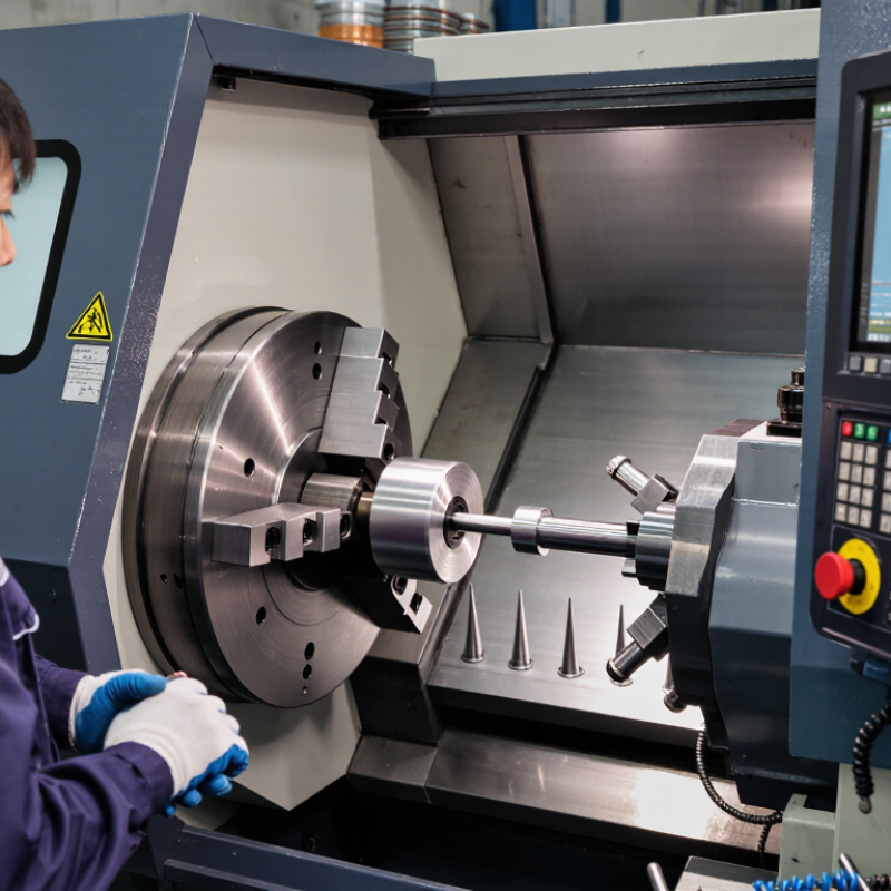
Understanding Waste Sources in Chipless CNC Spinning
Chipless CNC spinning produces no cutting chips, but it still creates waste. Common losses include oversized blanks, trimmed edges, wrinkled walls, cracks, and failed first-piece samples. Excess material often disappears during final trimming. Poor tool alignment can also damage several parts before anyone notices. That is expensive.
Measure the finished profile before selecting the blank diameter. A small trimming allowance is useful, but excessive allowance becomes scrap. Review the tool path in simulation, then run a controlled dry cycle. Check chuck alignment, roller position, feed rate, and forming pressure. Small errors can leave deep marks on the metal surface. They can also cause repeated rework.
Material variation creates another hidden source of waste. Thickness, hardness, and surface condition may differ between batches. Record these changes with each setup. Use gradual forming passes when the wall is thin or the shape is deep. Lubrication should be consistent, not excessive. Too little increases friction; too much can contaminate surfaces and complicate handling. Inspect the first part at critical diameters and wall sections. Reuse suitable offcuts for smaller components when quality permits. Separate clean metal scrap from contaminated waste.
Zero waste sounds attractive. It is rarely realistic. In practice, the biggest improvement may come from preventing one failed batch, not chasing perfect numbers. Some workshops measure scrap by weight only, which hides the cost of inspection time, energy, and delayed production. That method needs reconsideration.
Estimated waste-reduction opportunities for a standardized 1,000 kg production batch.
The largest gains usually come from optimizing blank size and nesting, stabilizing forming parameters, and reducing setup losses. Tool alignment, lubrication control, in-process inspection, and reuse of suitable offcuts further reduce trim waste, defects, and material consumption.
Planning material use begins with the finished profile, not the raw sheet. Measure the required blank diameter, thickness, and forming allowance from actual trials. A small allowance prevents tearing, but excessive stock becomes avoidable trim. Measure the blank.
For chipless CNC spinning, compare several blank diameters before releasing a job. Record flange waste, edge trimming, and rejected parts separately. This reveals whether the tooling or the blank plan causes losses.
Digital nesting can also place smaller blanks inside larger remnants, when thickness and surface condition remain acceptable. Keep remnants labeled by alloy, temper, thickness, and heat number. Mixed scrap is harder to reuse and less valuable.
Material selection deserves equal attention. The International Aluminium Institute reports that recycled aluminium requires about 5% of the energy used for primary aluminium production in its 2021 pathway analysis. Clean, segregated offcuts therefore have measurable value. The United Nations Environment Programme’s Global Resources Outlook 2024 reports that global resource extraction has tripled since 1970. Every unnecessary blank adds pressure to that expanding material system.
A practical target is to review yield weekly. Compare planned blank weight with shipped part weight. This sounds basic. It often exposes quiet losses. Some teams optimize diameter but ignore setup trials, scratches, and rejected first pieces. That is where the plan needs honest revision. Test one smaller blank only after confirming wall thickness, springback, and dimensional stability. ISO 14051’s material-flow-cost approach supports tracking these losses as production costs, not merely scrap.
Chipless CNC spinning reduces scrap, but it does not eliminate waste. Poor toolpaths can create excess forming passes, uneven wall thickness, and rejected parts. Use a smooth spiral path with fewer reversals. Keep tool engagement consistent around the workpiece. This reduces sudden loads and surface correction work.
Cutting parameters still matter, even without conventional chips. Set feed rate, spindle speed, and forming pressure from verified trial data. Excessive speed can heat the blank and distort its profile. Low feed rates may increase cycle time and energy use. The U.S. Department of Energy’s 2022 Industrial Decarbonization Roadmap states that industry produces about 30% of U.S. greenhouse gas emissions. Efficient parameter selection supports both material and energy reduction.
Machine setup deserves equal attention. Center the blank carefully, check tool alignment, and measure runout before production. A small offset can multiply rejects during a long batch. Use dry runs and in-process dimensional checks before increasing production speed. ISO 14955-1 provides a framework for evaluating machine-tool energy performance, which can guide measurement during setup and operation.
Measure actual results. Not assumptions. Record blank weight, cycle time, rejected parts, and energy consumption per component.
In practice, operators often optimize feed rate first and overlook fixture stability. That mistake is common. A balanced setup may save more material than a faster toolpath.
In chipless CNC spinning, waste often begins as a small process drift. A slightly misaligned blank can create wrinkles, thinning, or an uneven rim. Operators should verify blank diameter, thickness, and surface condition before loading. Then, calibrate the mandrel, roller position, and clamping pressure at scheduled intervals. These checks prevent defects before material is committed to a finished part. They also create dependable production records.
In-process monitoring provides the clearest control. Load cells can reveal unusual forming force, while spindle feedback exposes speed changes. A sudden force spike deserves an immediate stop, not a hopeful adjustment. During production, probe checks or non-contact scanning can measure wall thickness, diameter, and profile accuracy. Set practical alarm limits from proven samples, not guesswork. Tool wear needs equal attention. Track roller edges, lubrication flow, and cycle counts. Replace worn tooling before it marks the surface or changes the shape.
The seventh control is disciplined defect analysis. Photograph rejected parts, record machine settings, and connect each defect to its operation. This makes corrective action measurable. I have found that operators often notice subtle vibration before software flags it. Their observations should enter the quality record. Still, human judgment can vary. Use checklists and repeat measurements to reduce that weakness. No process is perfectly stable. A missed sensor warning, a dirty probe, or an overconfident adjustment can still produce scrap. Reviewing these failures honestly improves inspection plans and keeps waste from returning unnoticed.
Recovering, Reusing, and Tracking Remaining Materials
Chipless CNC spinning reduces machining swarf, but it does not eliminate waste. Remaining blanks, trimmed edges, setup pieces, and rejected parts still need control. In production, I have found that a labeled recovery bin works better than an unlabeled “scrap” container. Record alloy, thickness, diameter, heat number, weight, and source machine immediately. Small details matter.
The Ellen MacArthur Foundation’s Circularity Gap Report 2024 estimated that only 7.2% of the global economy was circular. This figure shows why material recovery must become a measurable process. Separate reusable blanks from contaminated or damaged pieces. Reuse suitable remnants for prototypes, collars, smaller spun parts, or setup trials. Keep a minimum-size rule, though. Oversized leftovers may become inventory nobody uses. That is a common failure.
Tracking should connect each remnant to a production order and storage location. A simple spreadsheet can work, but barcode records reduce manual errors. Review recovery weight, reuse rate, disposal weight, and rejected-part causes every month. The U.S. Environmental Protection Agency recommends measuring waste generation and diversion to identify improvement opportunities. Use the same measurement period each month. Otherwise, comparisons become unreliable.
Operators should also photograph unusual defects, such as wrinkles near the chuck or uneven wall thinning. Those images support practical training and root-cause reviews. Do not hide poor results. A low recovery rate may reveal bad blank sizing, excessive trimming, or weak material handling. The process needs refinement.
| No. | Waste-Minimization Method | Material or Waste Stream | Recommended Operating Practice | Key Measurement | Typical Planning Target | Review Frequency |
|---|---|---|---|---|---|---|
| 1 | Separate and Label Remaining Materials | Sheet blanks, discs, edge trim, setup pieces, and rejected parts | Use clearly marked containers for each alloy, thickness, and material condition. Keep aluminum, steel, stainless steel, and other alloys physically separated to prevent contamination and incorrect reuse. | Material identification accuracy and contamination rate by mass | 100% of containers labeled; contamination below 2% | Every shift |
| 2 | Optimize Blank Size and Forming Layout | Unused sheet area and oversized blanks | Calculate the minimum blank diameter required for the finished geometry, flange allowance, draw depth, trimming allowance, and material springback. Validate the design with first-article measurements before standardizing the blank size. | Material utilization = finished-part mass ÷ blank mass × 100 | Use the smallest blank that meets dimensional and forming requirements; track improvement against the approved baseline | For every new part or design change |
| 3 | Reuse Suitable Offcuts and Remnants | Usable discs, partial sheets, trim rings, and short-length remnants | Record outside diameter, inside diameter, thickness, alloy, temper, and quantity. Reserve remnants for smaller components, test pieces, setup trials, or secondary operations where the material specification is acceptable. | Remnant reuse rate = reused remnant mass ÷ available remnant mass × 100 | Inspect and catalogue 100% of reusable remnants; review any remnant stored longer than 90 days | Weekly |
| 4 | Recover and Recycle Metal Trim | Trim rings, edge cuts, rejected blanks, and non-reusable formed parts | Keep ferrous and non-ferrous scrap streams separate. Remove foreign materials such as plastic, wood, and excessive lubricant before weighing and sending material to an approved metal recycler. | Recycling rate = recycled metal mass ÷ total metal waste mass × 100 | Record 100% of metal waste by alloy family and maintain a traceable transfer record | At each collection or shipment |
| 5 | Control Lubricant and Coolant Use | Forming lubricant, coolant, contaminated wipes, and liquid waste | Apply only the amount required for forming stability and surface quality. Use drip trays, filtration, and scheduled inspections to prevent leaks and reduce unnecessary disposal of reusable fluids. | Fluid consumption per finished part and recovered-fluid volume | Measure in litres per 100 parts; investigate unexplained increases of more than 10% | Daily measurement; monthly trend review |
| 6 | Reduce Setup Rejects Through Standardized Parameters | Trial blanks, first-off rejects, wrinkled parts, cracks, and dimensional rejects | Use documented spindle speed, feed rate, tool position, lubrication condition, blank clamping force, and pass sequence. Confirm the first acceptable part before releasing the production batch. | Setup scrap rate = setup rejects ÷ total setup pieces × 100 | Set a process-specific limit and investigate any week-over-week increase of more than 10% | Each setup; weekly review |
| 7 | Track Material From Receipt to Final Recovery | Purchased blanks, work-in-process, finished parts, remnants, rejects, and recycled scrap | Assign a batch or heat reference to incoming material and record material issued, finished output, reusable remnants, process loss, and recycled scrap. Reconcile the material balance at the end of each production order. | Material balance variance = input mass − output mass − recorded waste mass | Keep unexplained variance within ±2% of input mass | Each production order; monthly management review |
Measurement note: The targets shown are practical internal-control ranges rather than company-specific performance claims. Actual limits should be adjusted for alloy, thickness, part geometry, surface-quality requirements, and local recycling regulations.
Yes. It avoids cutting chips but still produces trimmed edges, wrinkles, cracks, and rejected parts. Waste remains.
Measure the finished profile before choosing the blank diameter. Keep only a small trimming allowance. Too much allowance becomes scrap.
Review the tool path in simulation before production. Check chuck alignment, roller position, feed rate, and forming pressure. Use a controlled dry cycle.
Thickness, hardness, and surface condition can change between batches. Record these differences during every setup. Material variation is easy to underestimate.
Use gradual forming passes for thin walls or deep shapes. Keep lubrication consistent. Too little increases friction, while too much may contaminate surfaces.
Check critical diameters and wall sections carefully. Look for deep marks, uneven thinning, wrinkles, and cracks. A missed defect can affect several parts.
Separate clean offcuts from contaminated or damaged pieces. Use suitable remnants for prototypes, collars, smaller parts, or setup trials. Some leftovers still become unused inventory.
Record the alloy, thickness, diameter, heat number, weight, source machine, order, and storage location. A labeled bin prevents confusion. Labels are surprisingly important.
Track recovery weight, reuse rate, disposal weight, rejected-part causes, inspection time, energy, and delays. Weight alone hides important costs. That method needs reconsideration.
Usually not. Preventing one failed batch may matter more than chasing perfect numbers. The process can improve, but it will remain imperfect.
Minimizing waste in chipless CNC spinning begins with understanding where material losses occur, including oversized blanks, inaccurate forming, setup errors, trimming, and rejected parts. A practical approach is to plan material usage carefully, choose blanks that closely match the required dimensions, and account for forming allowances without excessive excess. Efficient toolpaths, suitable cutting and forming parameters, and stable machine setup can reduce unnecessary material removal, energy use, and rework. In this context, learning how to minimize production waste using chipless cnc spinning methods helps manufacturers improve both resource efficiency and production consistency.
Waste reduction also depends on prevention and recovery. In-process monitoring, dimensional checks, and quality-control procedures can identify problems early before multiple parts are affected. Remaining sheet sections and usable offcuts should be sorted, tracked, and reused whenever their size and condition permit. Recording material consumption, defect causes, and recovery rates creates a clear basis for continuous improvement. Together, these practices lower waste, control costs, and support a more efficient chipless CNC spinning workflow.

ZRF Spinning