CNC spinning should produce smooth, controlled metal flow. Yet wrinkled flanges, split edges, and uneven walls still appear in experienced workshops. The question, “why is my cnc spinning machine causing material wrinkling and cracking,” usually has several answers. Blank thickness, alloy condition, tool alignment, feed rate, and lubrication can interact within one cycle.
Industry guidance supports a process-based diagnosis. ASM Handbook, Volume 14A, Metalworking: Sheet Forming, identifies excessive compression, unstable material flow, and local thinning as common forming risks. ISO 6892-1 also reminds engineers that tensile behavior changes with material grade, temperature, and testing direction. These details matter when a stainless-steel blank cracks at the rim, while a similar aluminum blank wrinkles near the chuck.
Small changes matter.
UNIDO’s manufacturing performance reports continue to show strong pressure on factories to improve productivity, consistency, and resource efficiency. Recent smart-manufacturing surveys from Rockwell Automation also emphasize process monitoring and quality data. However, automation cannot correct a poorly centered blank or a worn roller. That assumption needs reconsideration.
This 2026 guide examines practical CNC spinning machine wrinkling and cracking fixes. It connects shop-floor symptoms with measurable causes, including roller clearance, spindle speed, reduction ratio, lubrication coverage, and material hardness. Readers will find inspection steps, parameter checks, and corrective actions suitable for production environments. The recommendations should still be validated through trial parts, metallurgical checks, and documented process results. A perfect diagnosis is uncommon. Reliable improvement comes from controlled evidence, not guesswork.
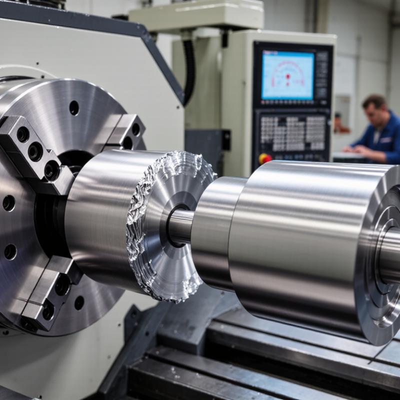
CNC spinning machine wrinkling and cracking begin with unstable material flow, not with one faulty setting. Wrinkles form when the flange region enters compression and loses shell stability. Cracks appear when local tensile strain exceeds the material’s forming limit. ASM Handbook, Volume 14B, identifies thickness, anisotropy, friction, and strain hardening as key variables in sheet-metal forming.
A practical diagnosis starts at the part surface. Broad, regular waves near the flange often indicate excessive feed, weak blank holding, or insufficient support. A sharp crack near the nose usually suggests excessive reduction, a small tool radius, poor lubrication, or material anisotropy. Check the actual sheet thickness at several points. ISO 6892-1 tensile testing can provide yield strength, elongation, and repeatable material data before production trials.
Process records matter. Log spindle speed, feed rate, tool path, lubricant condition, and temperature for every trial. Then compare the damaged zone with a forming-limit diagram from ASM technical data. Reduce feed in small steps, improve blank restraint, and increase the tool radius cautiously. More lubrication is not always better; it can reduce friction so much that the blank slips unpredictably. That detail is easy to miss. My own practical view is less comfortable: many “machine problems” are material-lot changes disguised as programming errors. A single inspection point cannot prove stability. Test several blanks, measure springback, and question results that look unusually perfect.
| Defect or Condition | Primary Cause | Typical Visual or Process Indicator | Verification Method | Corrective Action | Core Control Principle |
|---|---|---|---|---|---|
| Circumferential wrinkling | Excessive compressive stress in the unsupported flange or wall area. Common contributors include excessive axial feed, insufficient blank restraint, and an unfavorable roller path. | Ring-shaped folds, usually appearing ahead of the roller contact zone. The folds may become deeper during later passes. | Inspect the first visible wrinkle location, review the programmed feed rate, and check blank-holder or tailstock force. Confirm that the blank is seated evenly. | Reduce axial feed or distribute deformation over additional passes. Increase restraint gradually within the material and machine limits. Improve blank seating and use a smoother roller approach. | Keep compressive stress below the local buckling resistance of the unsupported sheet. |
| Localized wall wrinkling | Nonuniform contact caused by roller misalignment, an incorrect roller nose radius, excessive clearance, or local variation in material thickness. | Wrinkles appear only in one circumferential region or follow a repeating pattern at a fixed machine position. | Measure wall thickness around the circumference, inspect roller alignment, and compare the tool path with the mandrel profile. | Align the roller and mandrel axes, verify the roller nose geometry, correct excessive clearance, and remove burrs or contamination from locating surfaces. | Maintain uniform tool engagement and consistent support around the entire circumference. |
| Edge cracking | Excessive tensile strain at the rim, a sharp or damaged blank edge, insufficient edge preparation, or excessive deformation concentrated in the final pass. | Radial cracks begin at the open edge and may grow inward during subsequent forming. | Examine the edge under suitable lighting or magnification. Check blank diameter, edge burrs, material direction, and the final-pass reduction. | Deburr and round the blank edge, reduce the final-pass deformation, use more intermediate passes, and adjust the roller entry path to avoid an abrupt load increase. | Control peak tensile strain and avoid sharp geometric discontinuities at the free edge. |
| Meridional or longitudinal cracking | Localized thinning and excessive tensile stress along the generatrix. Possible contributors include an overly aggressive feed, an unsuitable roller angle, poor lubrication, or inadequate material ductility. | Cracks run approximately from the rim toward the base or along the principal forming direction. | Map wall thickness along the crack path, compare the actual profile with the drawing, and inspect for scoring or galling on the formed surface. | Reduce localized thinning, smooth the roller path, improve lubrication, use more forming passes, and confirm that the material condition is suitable for spinning. | Prevent excessive strain concentration and maintain adequate remaining wall thickness. |
| Cracks at the base or transition radius | The transition radius is too small for the material and reduction, or the roller path changes direction too sharply near the base. | Cracks occur where the wall changes angle, especially near a small radius or at the start and end of a pass. | Inspect the transition radius, compare the tool profile with the part drawing, and review roller acceleration and path curvature. | Increase the transition radius where design allows, use a staged path, reduce the local reduction, and remove abrupt direction changes. | Spread deformation through a smooth radius and avoid sudden changes in contact pressure. |
| Cracking after several passes | Work hardening, accumulated plastic strain, rising forming force, or insufficient intermediate annealing for the selected material and deformation level. | The part appears acceptable during early passes, but cracks develop later or after unloading. | Compare forming force by pass, review the total reduction, measure hardness if appropriate, and examine the fracture surface for signs of ductility loss. | Reduce the strain per pass, add a suitable intermediate heat treatment when permitted, and verify the material temper and heat-treatment condition. | Manage cumulative strain and material hardening instead of evaluating only the final pass. |
| Wrinkling followed by cracking | An initial fold creates a sharp local radius and concentrates strain. Continued rolling then stretches the folded area until it splits. | A visible wrinkle is followed by a crack at the fold crest or trough during a later pass. | Stop the process at the first sign of wrinkling and inspect the fold before applying additional passes. | Correct the wrinkling cause first. Do not attempt to flatten a severe fold with a high-force finishing pass; restart with corrected support and path conditions when necessary. | Treat wrinkling as a precursor defect because it sharply reduces local formability. |
| Wrinkles near the flange or unsupported area | The unsupported span is too large, blank-holder force is too low, or the flange is not adequately supported during the early forming stage. | Folds form outside or just ahead of the roller contact area while the supported region remains relatively smooth. | Check the unsupported span, holder pressure, blank diameter, and contact condition between the blank and support components. | Increase support or restraint in controlled increments, shorten the unsupported span where feasible, and begin with a less aggressive roller entry. | Increase structural support before increasing forming force. |
| Surface scoring or galling with later cracking | Inadequate lubrication, excessive contact pressure, rough or damaged tooling, or incompatible tool and workpiece surface conditions. | Scratches, smeared material, built-up deposits, and localized discoloration appear before cracks develop. | Inspect roller and mandrel surfaces, check lubricant coverage, and compare defect locations with tool contact marks. | Clean and polish tooling as appropriate, restore the correct surface condition, apply a suitable lubricant consistently, and reduce excessive contact pressure. | Reduce friction and prevent surface damage that can act as a crack initiation site. |
| Uneven wall thickness | Blank eccentricity, mandrel runout, roller misalignment, inconsistent feed, or variation in the incoming sheet thickness. | One side is thinner or thicker than the opposite side; cracks may repeatedly occur at the thinnest location. | Measure thickness at multiple angular positions and axial locations. Check runout with a dial indicator and verify blank centering. | Re-center the blank, correct runout, align the tooling, stabilize feed motion, and segregate material with excessive thickness variation. | Stabilize geometry and process symmetry before optimizing deformation parameters. |
| Excessive forming force or torque | Excessive reduction per pass, an unsuitable roller angle, inadequate lubrication, insufficient clearance, or a material condition with low ductility. | Servo overload alarms, unstable motion, tool chatter, sudden force spikes, or deformation that is concentrated in a narrow zone. | Trend force and torque by pass, inspect for tool interference, and compare actual parameters with the qualified process window. | Reduce the reduction per pass, smooth the path, verify clearance and lubrication, and stop the cycle if force rises abnormally. | Use force and torque trends as early indicators of unstable forming. |
| Cracks caused by material or blank preparation | Low ductility, incorrect temper, inclusions, laminations, pre-existing edge damage, or a blank cut with excessive burrs. | Similar cracks occur in different machine settings or follow defects already present in the blank. | Inspect incoming blanks, compare material certificates with the specification, examine fracture surfaces, and test a sample from another sheet or batch. | Use verified material condition, improve blank-cutting and deburring practice, reject laminations or severe inclusions, and confirm suitability through a forming trial. | Separate material-related failures from machine- and parameter-related failures before changing the process. |
| Tool chatter and periodic surface waves | Insufficient stiffness, unstable contact, excessive feed, worn tooling, poor clamping, or a machine dynamic response that amplifies vibration. | Repeating waves or marks occur at regular spacing; local thickness variation and crack initiation may follow the wave pattern. | Compare wave spacing with spindle speed and feed, inspect clamping stiffness, and check tool wear and machine vibration. | Reduce the unstable feed or speed combination, improve clamping, replace damaged tooling, and use a smoother tool path. | Keep the forming system dynamically stable so that contact pressure remains uniform. |
| Dimensional springback with apparent cracking risk | Elastic recovery after unloading, insufficient sizing, or residual stress from uneven deformation. High correction force may then create secondary damage. | The part opens away from the mandrel after release, and cracks appear during aggressive correction rather than during normal forming. | Measure the unloaded profile, compare it with the in-process profile, and inspect the correction operation for local overload. | Use controlled sizing or calibration passes, distribute correction over a larger area, and avoid forcing the part into tolerance in one high-load operation. | Control residual stress and springback through balanced deformation rather than excessive final-pass force. |
Process values should be qualified for the specific material, thickness, diameter, tool geometry, machine stiffness, lubrication system, and drawing tolerances. Any parameter change should be validated with dimensional inspection, wall-thickness mapping, and surface and crack inspection.
Wrinkles often begin in the flange, not the visible wall. Low blank-holder force may allow buckling. Excessive lubrication can reduce local support. Mark the first damaged area with a fine pen.
Wrinkles appear as buckled or folded areas. Cracks often start near a sharp tool radius. They may follow a thinning zone. Visual inspection alone can mislead.
Measure wall thickness on a grid around the damaged area. Check several angular positions. Compare results with material certificates and tensile-test data. One reading is not enough.
Review roller path, feed rate, forming angle, tool clearance, and lubricant volume. Also check spindle speed and forming temperature. Machine logs may reveal gradual changes. Operators sometimes remember settings incorrectly.
Increase local support carefully or reduce deformation speed. Do not solve every wrinkle with more force. Excessive pressure may damage the surface. The best setting may still need confirmation.
Use a larger tool radius when the edge is too sharp. Consider fewer severe passes. Intermediate heat treatment may help hardened material. Improve edge preparation and inspect material variation.
Record blank thickness, material batch, lubrication volume, roller feed, spindle speed, and temperature. Test several material batches. Use one controlled variable at a time. Real production conditions matter more than a perfect trial.
Inspect the first part, the tenth part, and the final part. Use control charts for thickness and defect frequency. Keep tool-maintenance records beside production data. Gradual wrinkling is easy to miss. That weakness should stay visible.
This guide explains the main causes of wrinkling and cracking in CNC spinning operations, including excessive forming pressure, incorrect tool alignment, unsuitable material properties, poor lubrication, and unstable machine settings. It also addresses the common question, “why is my cnc spinning machine causing material wrinkling and cracking,” by presenting a practical diagnostic approach. Operators can learn how to inspect defect patterns, check workpiece clamping, verify roller position, and review feed rate, speed, and forming passes before making adjustments.
The article then provides step-by-step setup checks to reduce forming defects and improve consistency. It covers material preparation, tooling condition, clearance control, lubrication selection, and controlled parameter changes. Finally, it explains how to validate the process through sample runs, dimensional inspection, repeatability checks, and documented production standards. By combining systematic troubleshooting with preventive maintenance and ongoing process monitoring, manufacturers can reduce scrap, extend tooling life, and achieve more reliable CNC-spun parts over the long term.

 ZRF Spinning